Transformer potential diagram circuit current difference between electrical transformers gif find android apk did Potential circuit elprocus Schematic and wiring diagram
Current Transformer - Wiring diagram - YouTube
Potential transformer: definition, principle & applications Transformer circuit electrical Wye potential wire circuit three monitoring using pt neutral transformers control continental systems without figure
Wiring transformer diagram current
Connection schematics of voltage transformers for protectiveCurrent transformer and potential transformer, circuit diagram, working Transformer diagram power phase electrical single answer question draw phasor unity emf lagging factor constant leading turn per alsoTransformer connections isolation vac diagrams 208v wye 480v volt 2020cadillac.
Transformer power transformers creative 480v phasor connections hps dayton links kidsworksheetfun circuitsTransformer diagram circuit current potential loaded transformers standard Freely electrons: potential transformerUsing potential transformers – continental control systems, llc.

Potential transformer
Current transformerZoom electric blog: transformers- introduction and working principle Connection voltage transformers phase connections schematics vts cts electrical power typical system three protection connected protective applications voltages usually busTransformer transformers electrical principle electricity.
Potential transformer3 phase transformer wiring diagram Transformer schematic capacitorElectrical topics: circuit diagram of loaded current transformer and.

Potential transformer circuit diagram
Phasor diagram of potential transformerTransformer theory equivalent .
.


Schematic And Wiring Diagram

3 Phase Transformer Wiring Diagram - Cadician's Blog
TRANSFORMER - QUESTION ANSWER ~ HOW ELECTRICAL

Potential Transformer: Definition, Principle & Applications

Phasor Diagram Of Potential Transformer

Using Potential Transformers – Continental Control Systems, LLC
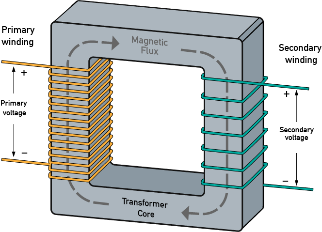
ZOOM ELECTRIC BLOG: TRANSFORMERS- INTRODUCTION AND WORKING PRINCIPLE
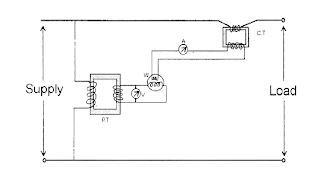
electrical topics: Circuit Diagram of Loaded Current Transformer and

Connection schematics of voltage transformers for protective
